It turns out the the process is really not that good of an idea for RAS owners.
They typically strip and then bake the items to get them clean and über dry. Then they coat and bake them to finish.
This process changes the tolerances of the aluminum parts enough to make them essentially worthless.
Live and learn... no more GWIs for me. It's "Go big or go home". I will keep my 925 and switch my attention to turning my flawed 3526 into a perfectly functioning Medium Arm GA.
Sunday, February 6, 2011

Thursday, December 9, 2010
Let's get it coated
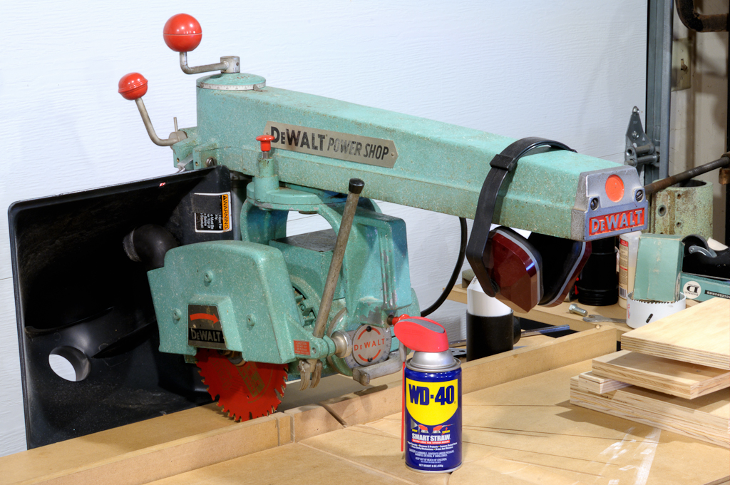
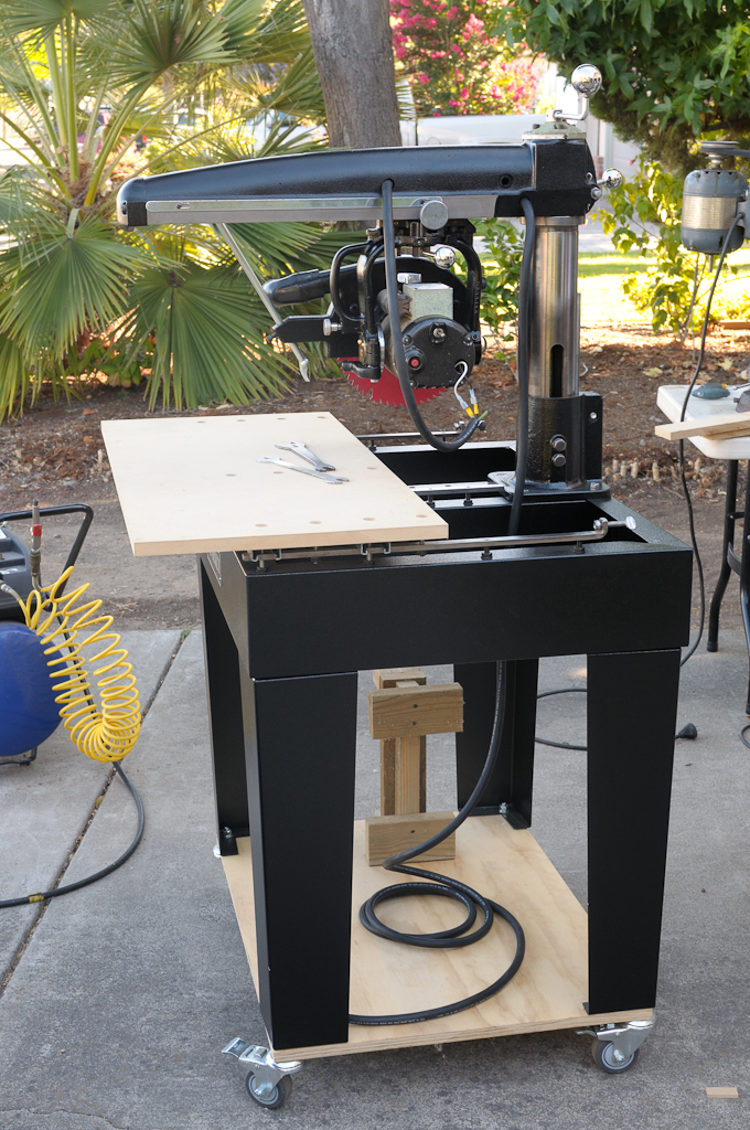
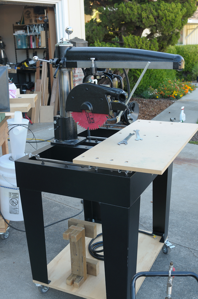
This is a radial arm saw with all the parts assembled. WD40 can for scale in all images.
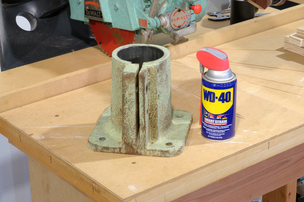
The column base (Cast Iron, has machined interior surface and threaded holes)
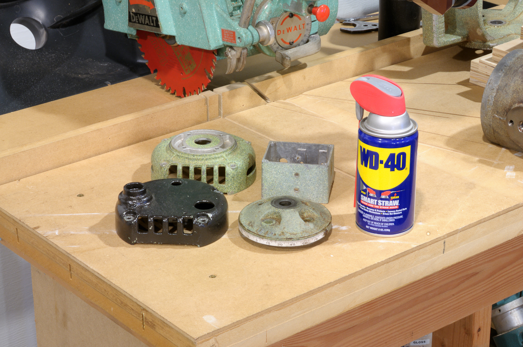
The two motor end bells (aluminum with machined surfaces for the bearings), thrust cap (cast iron) and electrical box for motor (aluminum)
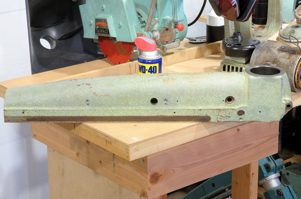
The arm (cast iron). It has machined surfaces where it rests against the column and threaded holes.
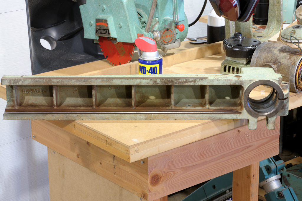
The arm on its side showing the machined "ways" where the roller carriage travels.
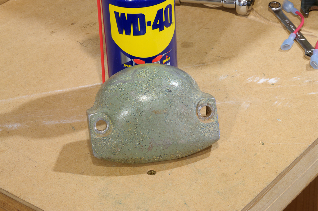
This is the "nose" cap that goes on the end of the arm. It's thick aluminum.
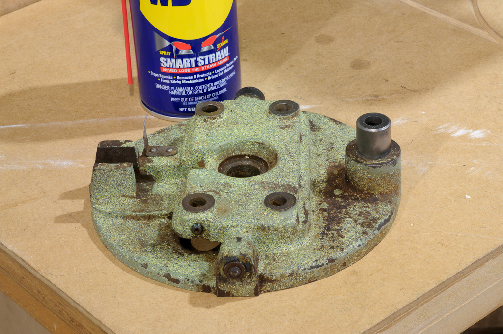
The roller carriage (cast iron) top view - it has threaded holes for set screws
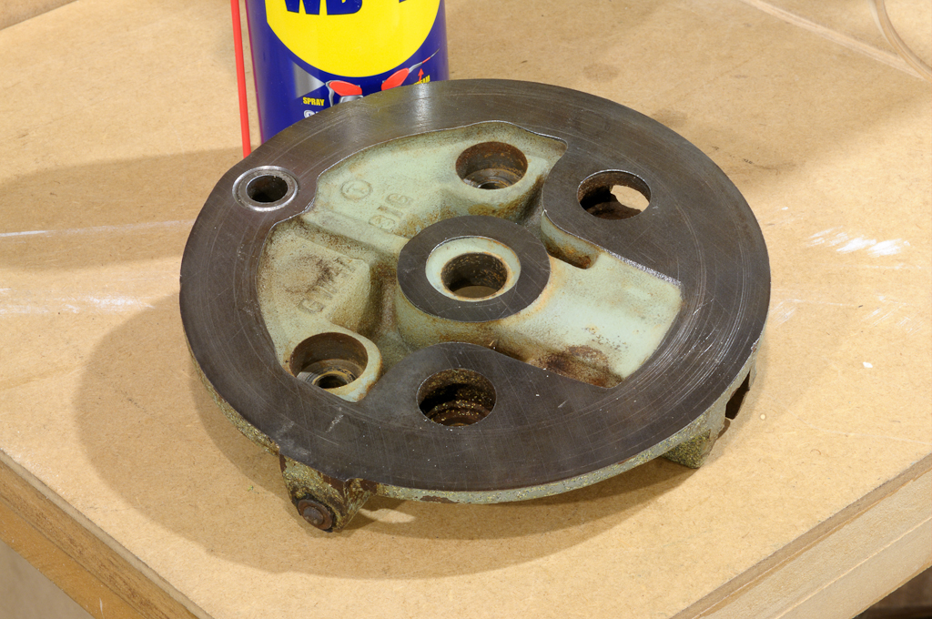
The roller carriage (cast iron) bottom view showing machined surfaces.
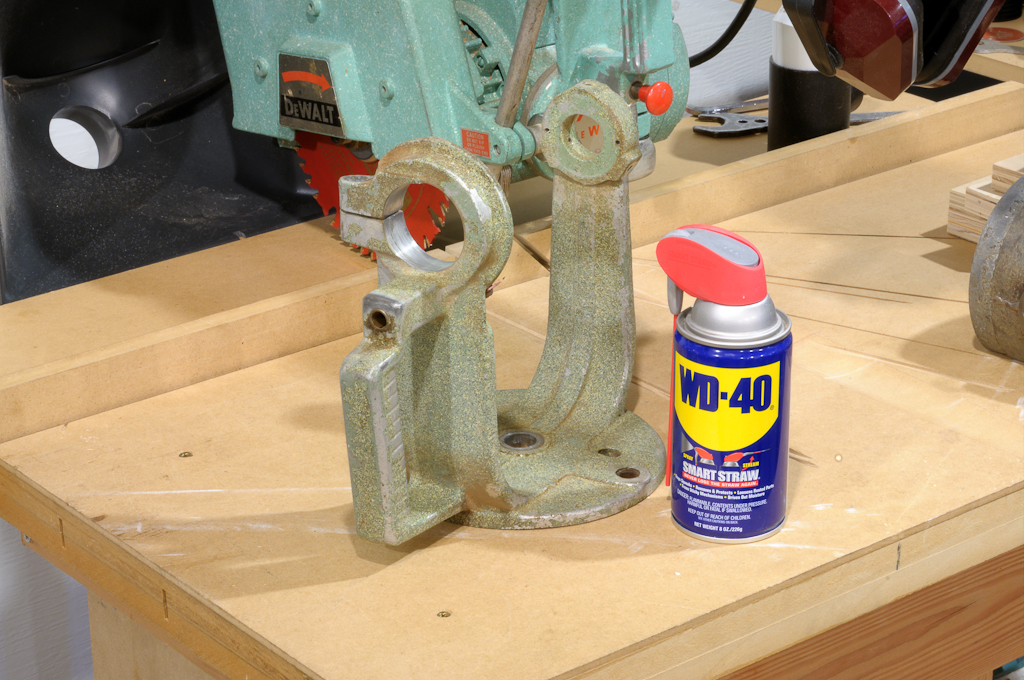
The yoke which holds the motor (Aluminum). It has threaded holes for set screws and a brass lined hole for the indexing pin.
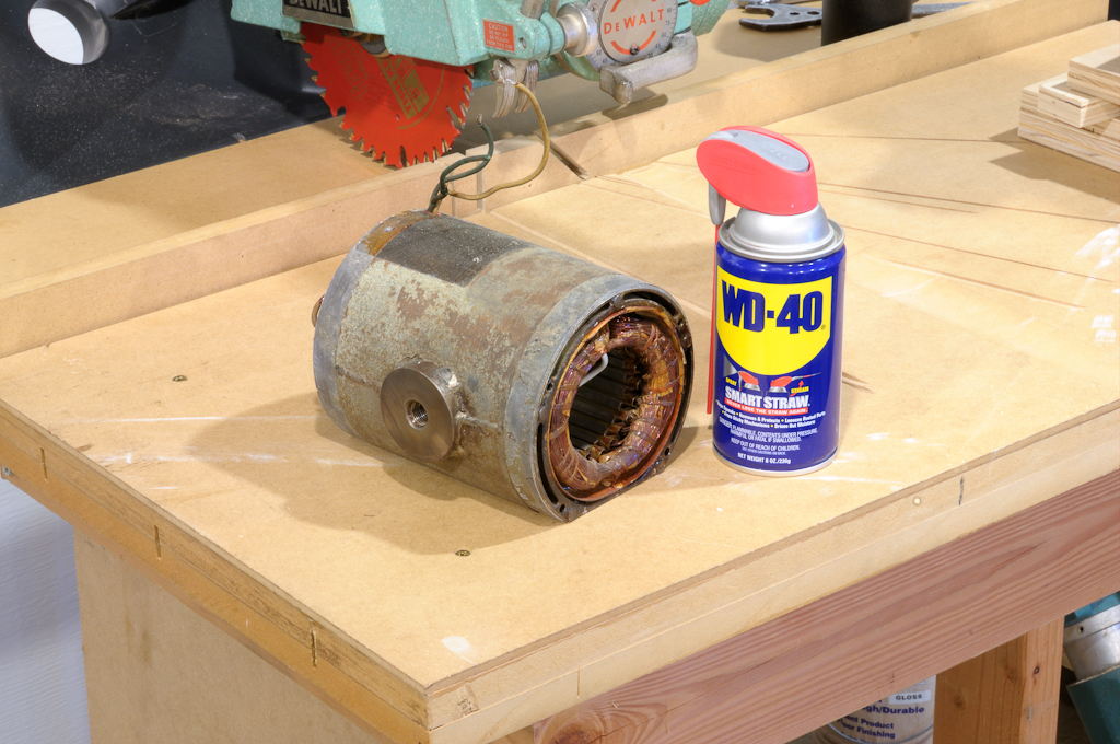
The motor housing (can't be powder coated as the insulation would melt in the oven)
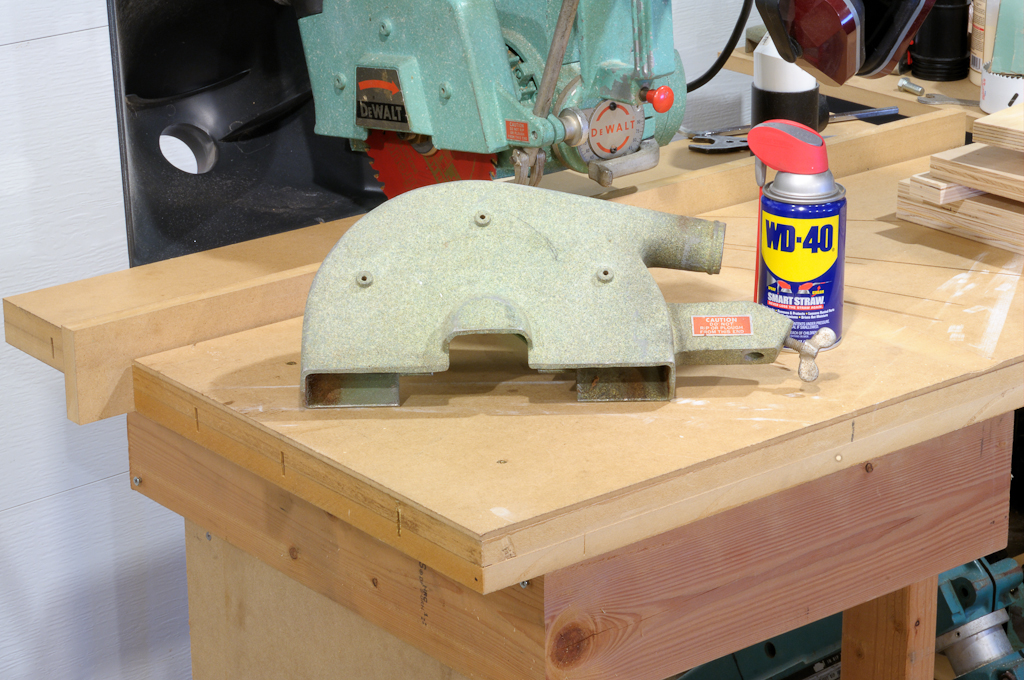
The blade guard (Aluminum). It has a large threaded hole.
Monday, August 30, 2010
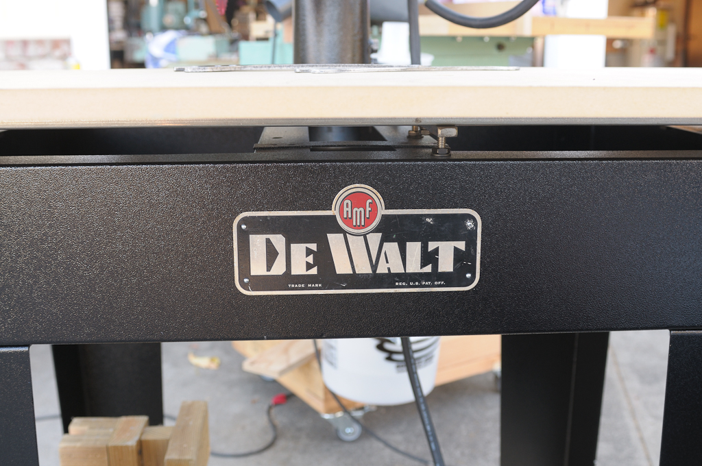
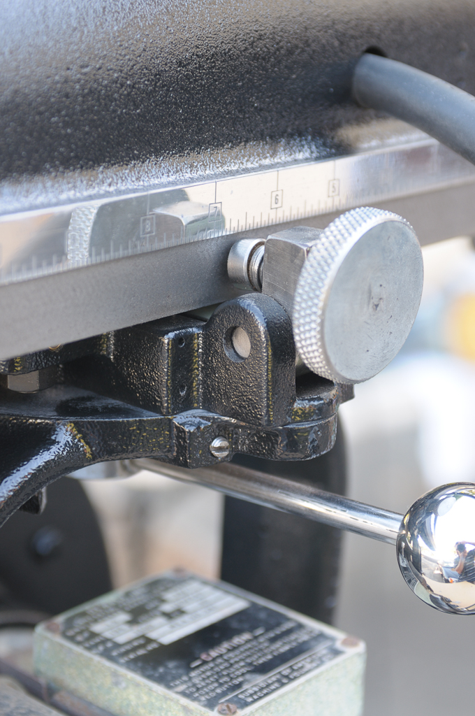
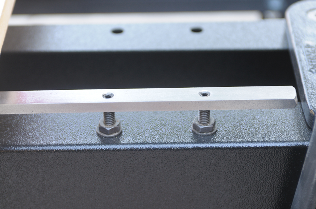
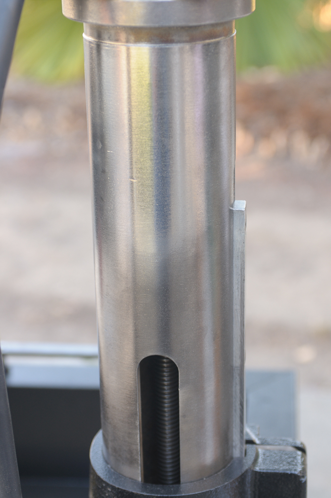
Tuesday, May 11, 2010

Tuesday, May 4, 2010
Electric Brake
I finally got my electric brake working for dual voltage. Here's a quick pic (click for larger version):

Left to right you see:
1) The main switch that sends voltage to the motor (two red leads) or the brake circuit (the long black cord wrapping around with black/white/green protruding)
2) The switch inside the brake circuit (120V) that makes sure 240V doesn't make it into the brake. The voltage coming into the circuit acts as both the "control" and the "controlled" current.
3) (on the left of the large white relay) a smaller relay that isolates the circuit from the voltage flowing to the motor
4) The "On Delay, Off Delay" relay (Macromatic TR-66122)
5) The rectifier
6) The transformer
What does it do? Basically, when the main switch is in the "Off" position 120V of AC are turned into 24V of DC and sent to the motor, stopping a 10" blade in about 6 seconds.
It works perfectly.
Parts were about $110 (The large relay is a $65 part). I'm sure it can be done cheaper but God knows I am no EE and this thing works like a champ.
I'll post more (proper diagram) later when I get more time.
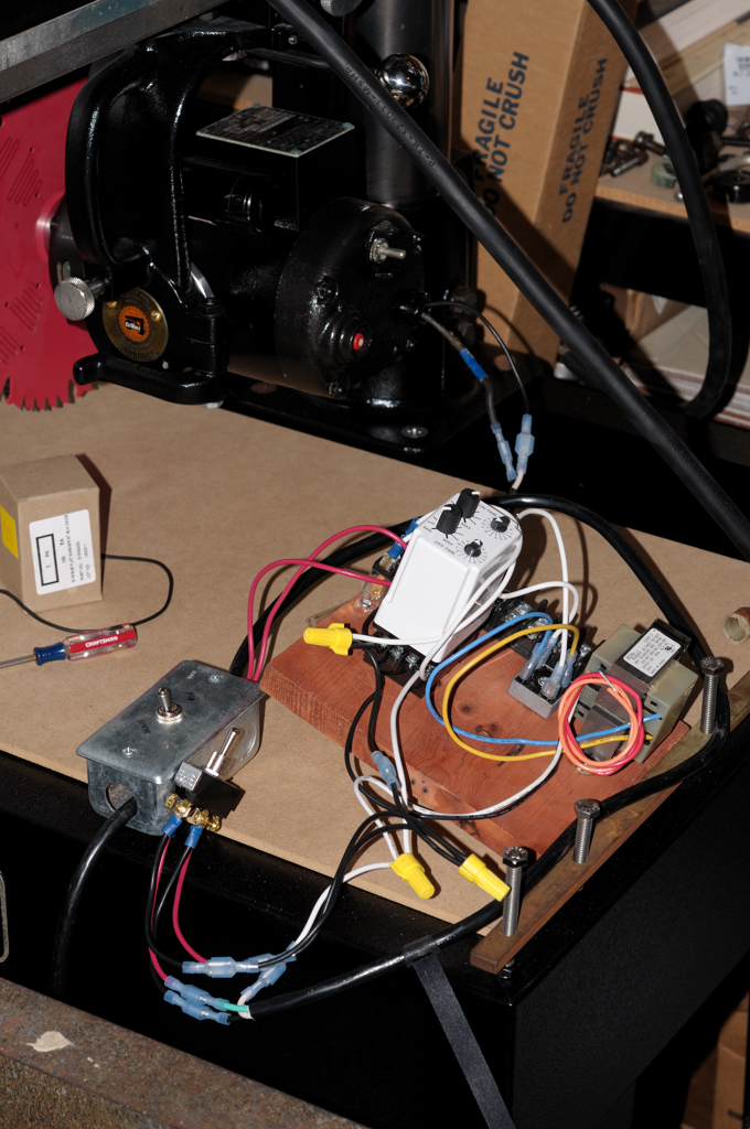
Left to right you see:
1) The main switch that sends voltage to the motor (two red leads) or the brake circuit (the long black cord wrapping around with black/white/green protruding)
2) The switch inside the brake circuit (120V) that makes sure 240V doesn't make it into the brake. The voltage coming into the circuit acts as both the "control" and the "controlled" current.
3) (on the left of the large white relay) a smaller relay that isolates the circuit from the voltage flowing to the motor
4) The "On Delay, Off Delay" relay (Macromatic TR-66122)
5) The rectifier
6) The transformer
What does it do? Basically, when the main switch is in the "Off" position 120V of AC are turned into 24V of DC and sent to the motor, stopping a 10" blade in about 6 seconds.
It works perfectly.
Parts were about $110 (The large relay is a $65 part). I'm sure it can be done cheaper but God knows I am no EE and this thing works like a champ.
I'll post more (proper diagram) later when I get more time.
Thursday, April 22, 2010
It Lives! Woooo Hoooo!
About damn time! I got the eBay motor, pulled out the fan, pressed it onto my rotor and put her back together.
It was still a bit rough.
I pulled it apart, made sure to shim the front bearing properly, and put it back together.
Much better but the rear was still groaning a bit.
I pulled it apart, noted the grease leaking out of the rear bearing, pulled it off the shoulder by 1/8" and pressed the motor back together.
Much, MUCH better. Still not perfect but almost acceptable. I threw an 8" blade on there and it actually helped (as well as masked the noise ;-).
It was still a bit rough.
I pulled it apart, made sure to shim the front bearing properly, and put it back together.
Much better but the rear was still groaning a bit.
I pulled it apart, noted the grease leaking out of the rear bearing, pulled it off the shoulder by 1/8" and pressed the motor back together.
Much, MUCH better. Still not perfect but almost acceptable. I threw an 8" blade on there and it actually helped (as well as masked the noise ;-).
Tuesday, April 13, 2010
Okie Dokie, fan on the way
I just won an auction for a GWI motor on EBay (my first ever purchase from there).
At this point I have two extra GWI motors without fans. I plan to find much cheaper MBF's out there to cannibalize off of and then turn a GWI carcass and a GWI motor into cash to support my habit.
Worst case I'll have two spare windings for GWI's.
Not long now...
At this point I have two extra GWI motors without fans. I plan to find much cheaper MBF's out there to cannibalize off of and then turn a GWI carcass and a GWI motor into cash to support my habit.
Worst case I'll have two spare windings for GWI's.
Not long now...
Subscribe to:
Posts (Atom)