Tuesday, May 11, 2010
Tuesday, May 4, 2010
Electric Brake
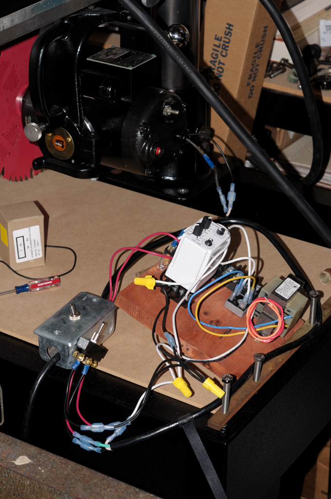
I finally got my electric brake working for dual voltage. Here's a quick pic (click for larger version):

Left to right you see:
1) The main switch that sends voltage to the motor (two red leads) or the brake circuit (the long black cord wrapping around with black/white/green protruding)
2) The switch inside the brake circuit (120V) that makes sure 240V doesn't make it into the brake. The voltage coming into the circuit acts as both the "control" and the "controlled" current.
3) (on the left of the large white relay) a smaller relay that isolates the circuit from the voltage flowing to the motor
4) The "On Delay, Off Delay" relay (Macromatic TR-66122)
5) The rectifier
6) The transformer
What does it do? Basically, when the main switch is in the "Off" position 120V of AC are turned into 24V of DC and sent to the motor, stopping a 10" blade in about 6 seconds.
It works perfectly.
Parts were about $110 (The large relay is a $65 part). I'm sure it can be done cheaper but God knows I am no EE and this thing works like a champ.
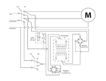
I'll post more (proper diagram) later when I get more time.
Left to right you see:
1) The main switch that sends voltage to the motor (two red leads) or the brake circuit (the long black cord wrapping around with black/white/green protruding)
2) The switch inside the brake circuit (120V) that makes sure 240V doesn't make it into the brake. The voltage coming into the circuit acts as both the "control" and the "controlled" current.
3) (on the left of the large white relay) a smaller relay that isolates the circuit from the voltage flowing to the motor
4) The "On Delay, Off Delay" relay (Macromatic TR-66122)
5) The rectifier
6) The transformer
What does it do? Basically, when the main switch is in the "Off" position 120V of AC are turned into 24V of DC and sent to the motor, stopping a 10" blade in about 6 seconds.
It works perfectly.
Parts were about $110 (The large relay is a $65 part). I'm sure it can be done cheaper but God knows I am no EE and this thing works like a champ.
I'll post more (proper diagram) later when I get more time.
Subscribe to:
Posts (Atom)